|
|
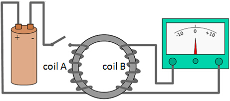
TransformerFaraday’s Iron Ring ExperimentFrom Electromagnetism, we know that
Therefore, At the moment when switch is closed, current in coil A increases from 0 to maximum which produces an increasing magnetic field in coil A linking coil B. By Faraday’s Law, there is an induced emf and hence induced current, thus, the pointer deflects momentarily. When switch remains closed, current in coil A is the same and hence there is no change in the magnetic field in coil A linking coil B. Thus, there is no induced emf. At the moment when switch is open, current in coil A decreases from maximum to 0 which produces a decreasing magnetic field in coil A linking coil B. By Faraday’s Law, there is an induced emf and hence induced current, thus, the pointer deflects momentarily in opposite direction. Conclusion: In order for induced current to flow continuously, we have to keep on opening and closing the switch to cause a change in magnetic field in coil A linking coil B. However, this is very troublesome and impractical. Therefore, we have to use an alternating current (a.c) supply to produce a continuous changing magnetic field and this leads us to the construction of transformers. TransformerA transformer is a device that can change a high alternating voltage to a low alternating voltage, or vice verse.
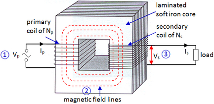
A transformer consists of two coils of wire:
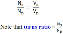
How does it work?
Types of Transformer
Efficiency of TransformerFor an ideal transformer (100% efficient),
However, in practical, there is always a power loss in transformer.
For a non-ideal transformer,
Input power in primary coil = power loss in transformer + output power in secondary coil Use of Transformer
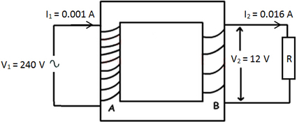
Example:
Answer:
(a) a.c supply input provides a continuous change in the magnetic flux linkage between the primary coil and secondary coil, and hence alternating a.c can be induced in the secondary coil. (b)(i) turns ratio = Ns / Np = Vs / Vp = 12 / 240 = 0.05 (ii) Efficiency = Output Power / Input Power * 100% = (12 * 0.016) / (240 * 0.001) * 100% = 80% (c)(i) No change as there is still a continuous change in magnetic flux linkage between primary and secondary coil, and hence emf still induced. (ii) I2 becomes 0 A as it is an open circuit now. Transmission of ElectricityDuring the transmission of electricity from power plant to households and industries, there is always a power loss in the form of heat (Joule heating = I^(2)*R) due to the resistance in the transmission cables.
There are two ways to minimize this power loss:
The below diagram shows how transmission of electricity happens in real life.
① Electricity produced in power plant is stepped up by a step-up transformer;
② High voltage electricity is transmitted through transmission cables; ③ Step-down transformers then step down the voltage to suitable values for use. Example:
The figure shows the voltage transmission of electric power from a power plant to industrial consumers. The power plant has a power output of 2500 kW and the total resistance of the transmission line is 0.5 Ω. (a) Calculate
(i) current in the transmission line (ii) voltage drop in the transmission line (iii) the power loss in the cables. (b) If the same power had been supplied at 5000 V, the current through the same cables would have been 100 times greater. Calculate the power loss under these circumstances. (c) Explain why power is better transmitted at a high voltage rather than low voltage. Answer:
(a) I = P / V = 2500 000 / 500 000 = 5.0 A Note that we cannot use V = IR here as 500 000 V is the output voltage from the transformer, not the potential difference across the transmission line. (ii) V = IR = 5 * 0.5 = 2.5 V Note that this is same as asking the potential difference across the transmission line. (iii) P = I^(2)*R = 5^(2) * 0.5 = 12.5 W OR P = VI = 2.5 * 5 = 12.5 W OR P = V^(2) / R = 2.5^(2) / 0.5 = 12.5 W Note that all three formulae of power can be used here. However, we have to use the correct value for V, which is the potential difference across the cables. (b) Inew = 5 * 100 = 500 A P = Inew^(2)*R = 125000 W By comparing part (aiii) and (b), we should understand why transmitting the power at high voltage reduces the power loss in the transmission cable. (c) At higher voltage, current transmitted through the cables will be lower as P= IV. Since power loss = I^(2)*R, the lower the current flowing in the cables, the lower the power loss. |
|


